


[068] Flyback Converter Development Part V - Control and Loop Gain
Flyback converter control and loop gain testing.
Introduction
This article is the fifth of a series in which Dr. Ridley shows the steps involved in designing and building an offline flyback converter. With full input voltage and full load applied, the control-to-output transfer function and loop gain is measured and compared to predictions.
Theory and Practice
The late and great analog guru Bob Pease had a quote which is always good to remember when designing power supplies:
“In theory, theory and practice are the same. In practice, they are different!”
I have been designing and measuring power supplies for over 30 years now. I don’t recall ever meeting one power supply that didn’t surprise me when testing it and making measurements. In this article, we will see how the measurement of a multi-output power supply does not conform to the predicted results, proving Bob’s theory above.
Flyback Converter Control Measurements
Figure 1 shows the schematic of the flyback converter ready for small-signal measurements. The AP300 frequency response analyzer was used to inject a signal into the circuit across the 20 ohm resistor. The output signal from the AP300 was isolated with the Universal Injector, a wide-band transformer capable of injecting into control circuits from 0.1 Hz to 30 MHz [1].
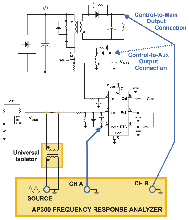
Figure 1: Schematic of the flyback converter with AP300 connections for measuring the control-to-output transfer functions.
When making control measurements of power supplies, it is commonplace to start the sweep frequency at 10 Hz, and stop at twice the switching frequency. Control information above half the switching frequency is of limited use, but it is helpful to be able to sweep past the switching frequency with an analyzer in order to verify its operating point. The lower frequency of 10 Hz is chosen since it is very important to verify that a converter has the proper gain at line frequencies and their harmonics. With a current-mode converter, the gain in this region can be very high, and the AP300 excels at measuring in this region of operation.
Channel A of the analyzer is connected to the output of the error amplifier of the control chip (Comp Pin 1), and Channel B is connected to either one of the two outputs of the power supply. In theory, these two points will track each other quite closely, but as we will see, this does not always happen in practice.
Figure 2 shows the theory and prediction of the control-to-output transfer function for the flyback converter. In this measurement, Channel B of the AP300 was connected to the main output of the power supply. The auxiliary output was loaded with 30 mA as described in Part IV of this series of articles
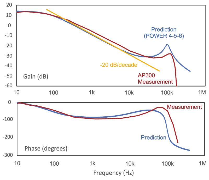
Figure 2: Prediction and measurement of the control-to-Main-output transfer function.
The blue curve of Figure 2 shows the control-to-output transfer function predicted by POWER 4-5-6 [3]. The red curve shows the actual measurements. As you can see from these two curves, there are significant discrepancies in the gain after 100 Hz or so, and again at half the switching frequency. This is quite normal for the first attempts at measuring and reconciling with models.
The modeling can be refined by incorporating the actual value of power supply output capacitor from measurements, and changing the predicted frequency to match the measured frequency. However it should be noted that in real-world power supplies, it is common that the measurements and predictions have deviations, and those shown in Figure 2 are actually in quite good agreement compared to what you may see on your particular power supply. It is one of the reasons that empirical measurements should always be done on a power supply. Models are often of limited accuracy in such a high-noise environment with nonlinear switching power supplies.
The gold curve of Figure 2 shows a -20 dB/decade slope asymptote. This illustrates that both the measured and predicted transfer functions roll off with this same slope, as would be expected for a current-mode system.
Control-to-Auxiliary-Output Measurement
The desired feedback point of the converter is not the main output, but the auxiliary output. If feedback can be taken from this output, the converter can be regulated without the use of an extra feedback amplifier (such as a TL431) and optocoupler. For low-cost bias
supplies, and for high-reliability supplies, elimination of these parts is important.
In Figure 1, Channel B of the AP300 analyzer connected to the auxiliary output feeding the bias of the control chip and the feedback compensation network.
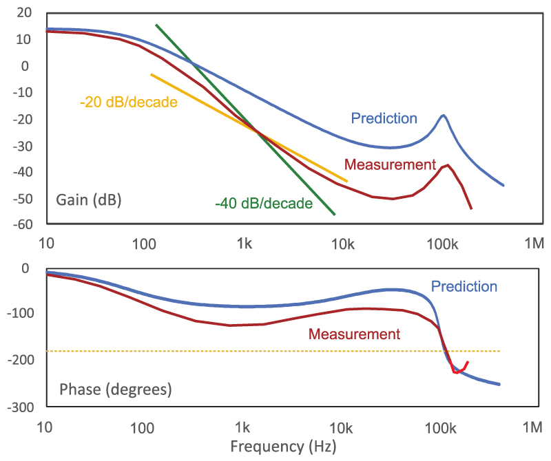
Figure 3: Prediction and measurement of the control-to-Auxiliary-output transfer function. There are substantial unexplained discrepancies.
Figure 3 shows the result of the auxiliary output measurement. There is now a very substantial difference between the measured and predicted transfer functions. At dc, the predicted blue curve and the measured red curve are in close agreement. However, once the first pole is reached the curves separate quite drastically, and at 10 kHz there is over 20 dB of difference between the two curves!
Two asymptotes are shown on the gain curve of Figure 3. It can be seen that the measured gain does not correspond to either a -20 or -40 dB/decade slope, which is quite an unusual result.
There are no models to explain this kind of deviation. It is not particular to this specific flyback converter, but this kind of event occurs with every converter with multiple outputs. It was observed in the coupled-inductor forward converter in reference [6].
Loop Gain Measurement
The deviations from predicted results also show up in the loop gain measurement of the flyback power supply. Figure 4 shows the test setup for measurement of loop gain with the AP300. The injection technique is exactly the same as in Figure 1, but the test points are changed.
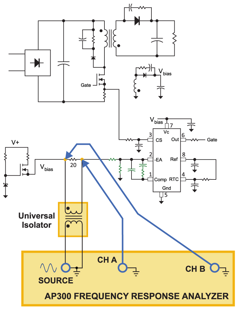
Figure 4: Loop gain measurement setup using the AP300 analyzer.
With this setup, the loop closed around the auxiliary output was measured, and the results are shown in Figure 5. As with the control-to-output measurement, there are very substantial differences between the prediction and the measurements.
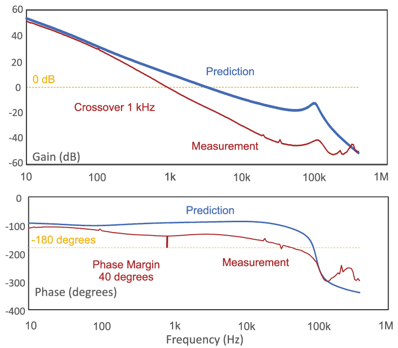
Figure 5: Loop gain measurements versus predictions. The discrepancies in the control-to-output measurement also affect the loop gain result.
There are a several design choices you have when running into this kind of situation. You can abandon the proposed control scheme of running off the auxiliary output, and go with something that adheres closer to predictions. Or, you can ignore the predictions, and just design the converter based upon the actual measurements. This is the most usual approach taken in industry since saving parts cost is usually more important than getting good agreement between measurement and theory.
If you are doing high reliability work where intense worst-case analysis is required, the multiple-output converters obviously present problems with predictability. Running a series of measurements is not a guarantee of ruggedness if there is no explanation of the parameters of the power supply causing the discrepancies.
Summary
The fifth part of this series on flyback circuit design highlights the issue of discrepancies between predicted and measured control characteristics for multiple output converters. This is a very important issue that has not been thoroughly addressed by researchers.
However, it is just one of the issues of converter design that make it such a challenging field. There are so many nonlinearities and parasitics involved in the control characteristics of power supplies, it is quite common for behavior to be unpredictable. In this case, it is essential that comprehensive measurements are made on multiple converter prototypes before a design is put into production.
While the flyback circuit is a simple example of the this kind of event, it can also be observed with much more complex power circuits, such as the LLC converter. Measurements are crucial as the complexity goes up since the circuit models are so often lacking in accuracy.
References
- Join our LinkedIn group titled “Power Supply Design Center”. Noncommercial site with over 7000 helpful members with lots of theoretical and practical experience.
- For power supply hands-on training, please sign up for our workshops.
- “Why you only need one injection isolator”
- POWER 4-5-6 software for power supply design
- Flyback Power Supply Development, Parts I – IV
- Power Supply Development Diary, Part XVI